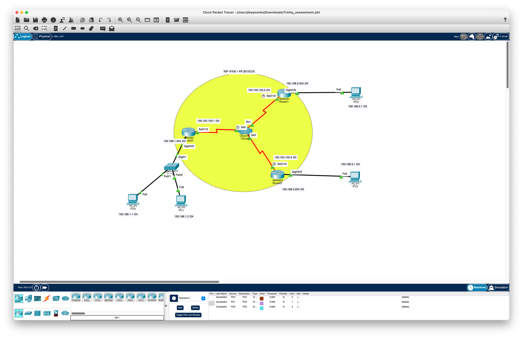
interface Serial0/1/0
 ip address 100.100.100.1 255.255.255.0
 encapsulation frame-relay
 no frame-relay inverse-arp
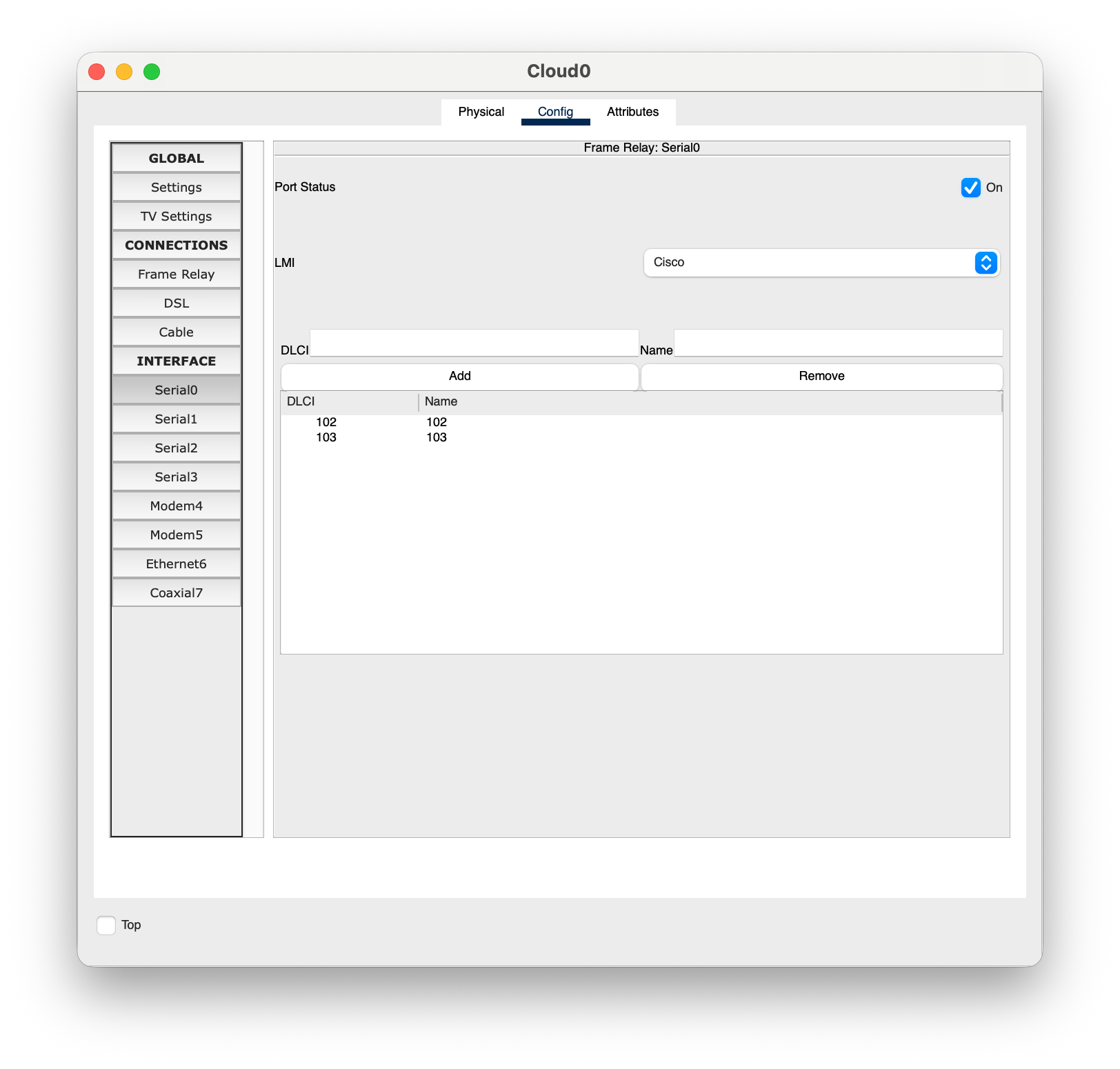
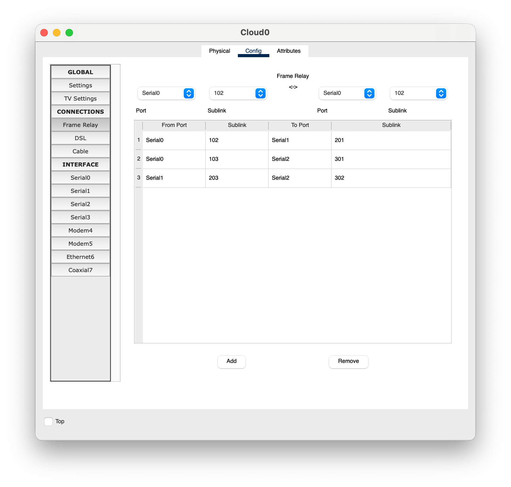
 frame-relay map ip 100.100.100.2 102 broadcast
 frame-relay map ip 100.100.100.3 103 broadcast
 no shutdown
interface GigabitEthernet0/0/0
 ip address 192.168.1.254 255.255.255.0
 no shutdown
router rip
 version 2
 no auto-summary
 network 100.0.0.0
 network 192.168.1.0
Router1
interface Serial0/1/0
 ip address 100.100.100.2 255.255.255.0
 encapsulation frame-relay
 no frame-relay inverse-arp
 frame-relay map ip 100.100.100.1 201 broadcast
 frame-relay map ip 100.100.100.3 203 broadcast
 no shutdown
interface GigabitEthernet0/0/0
 ip address 192.168.2.254 255.255.255.0
 no shutdown
router rip
 version 2
 no auto-summary
 network 100.0.0.0
 network 192.168.2.0
Router2
interface Serial0/1/0
 ip address 100.100.100.3 255.255.255.0
 encapsulation frame-relay
 no frame-relay inverse-arp
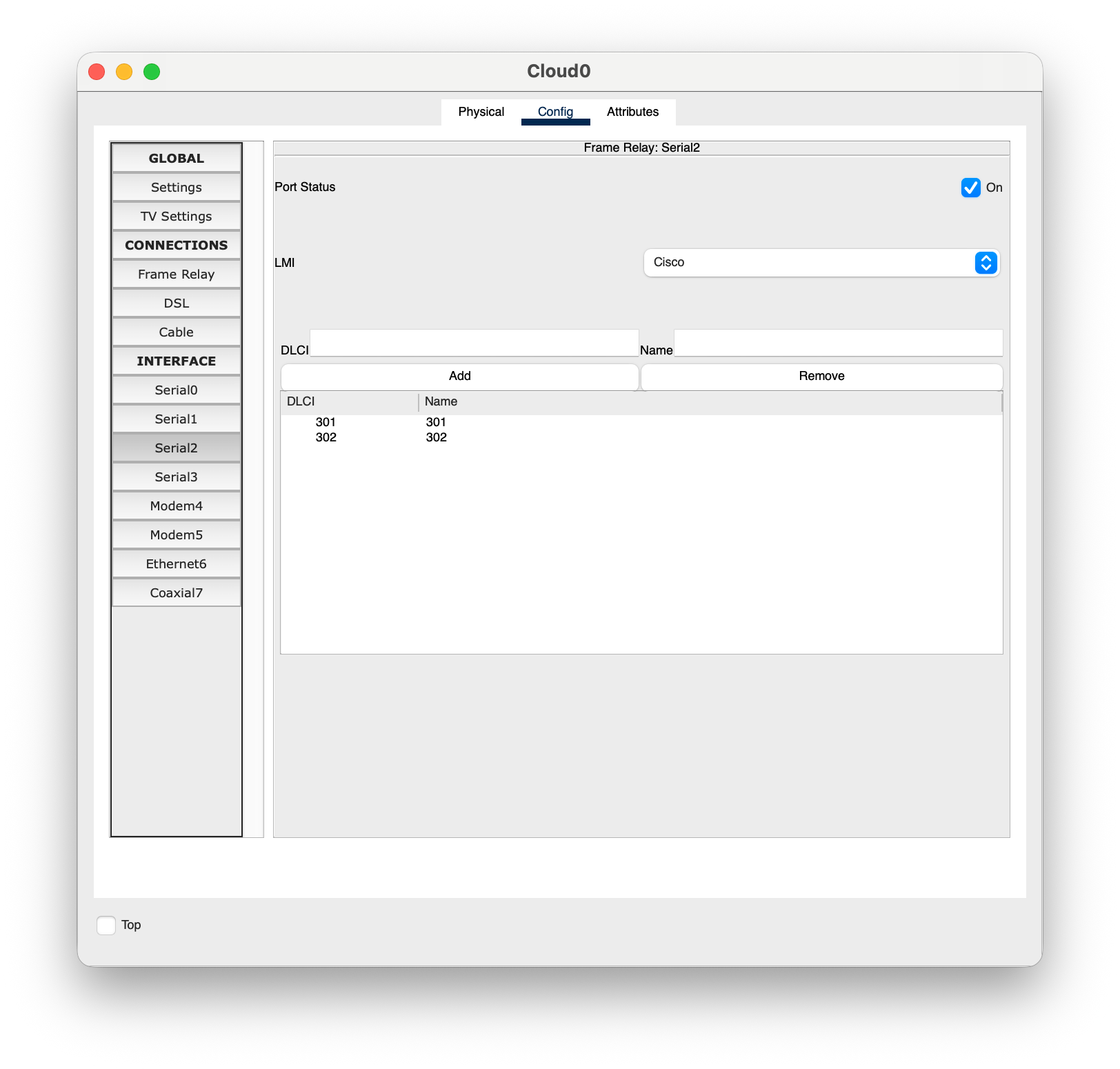
 frame-relay map ip 100.100.100.1 301 broadcast
 frame-relay map ip 100.100.100.2 302 broadcast
 no shutdown
interface GigabitEthernet0/0/0
 ip address 192.168.3.254 255.255.255.0
 no shutdown
router rip
 version 2
 no auto-summary
 network 100.0.0.0
 network 192.168.3.0